posted by Dave Arnold
Cooks love their thermometers. Thermocouple thermometers are especially loved because they are rugged, can measure extreme temperature ranges, have a wide range of available probes, and are fairly accurate once calibrated properly. But they can be expensive. This post is dedicated to making thermocouple probes affordable, by rolling your own.
Thermocouples work because of something called the Seebeck effect, which states that a circuit made of two different metals will generate a (tiny) voltage that changes with difference in temperature between the two sides of the circuit. A thermocouple thermometer is just two wires made of different metals and an amplifier to measure the voltage across them. Different types of thermocouple probes use different metals. The probe most popular with cooks is type K, which has one chromel wire (nickel/chromium) and one alumel wire (nicklel plus other stuff). For a good article on thermocouple types, check the Wikipedia page. The cool thing is you can buy wire and make your own thermocouples.
Everything needed to build almost anything in the world can be purchased from McMaster Carr. If you didn’t already know about McMaster, you are welcome. They have an easy to use website, everything is always in stock, and if you order before 6pm anywhere in the continental US, it arrives the next day at standard  ground shipping rates.  The downside is that their prices are quite expensive.
McMaster sells a wide variety of type K thermocouple wire. Here is a sample part number: 6579T38 ($1.26 a foot). You also need a thermocouple connector. Most themometers use “flat-pin mini” male connectors, part number 3869K35 ($3.21 a piece). If you want to make an extension cord for your thermometer, also order a female connector, part number 3869K34 ($3.74 apiece).
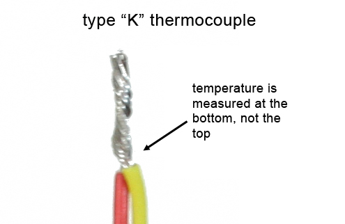
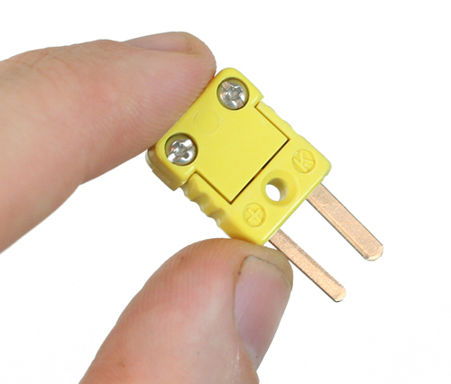
How to make a thermocouple
Simply strip the ends of the wires, twist them together, and, voila! thermocouple probe. All that’s left is to attach the connector. Unscrew the connector body, strip the ends of the wire on the connector end and screw them down to the terminals. Remember not to mess up the polarity— on type K thermocouples the RED is NEGATIVE and the YELLOW is POSITIVE. Calibrate your new probe in copious ice water. Done.  Note that the temperature is measured only from the first place the wires touch, not along the whole length of the twisted wire.
The above technique makes for a thermocouple that works well for most purposes. In moist, steamy environments or in situations with a lot of mechanical stess and thermal shock (like in our Red Hot Poker), a more permanent solution is sometimes needed. Here are three options:
- Use lead free solder to keep the twisted wires together. The solder doesn’t mess up the probe. Only use this technique at temperatures below the melting point of your solder, and try to use as little solder as possible (to keep down thermal mass).
- Encapsulate the twisted wires in epoxy or ceramic. Use a small amount because epoxy doesn’t conduct heat so well. There is a food grade epoxy putty with stainless steel powder that is good for applications below 250°F (McMaster 74575A69) and a non-food-grade ceramic/stainless putty good to 2000°F (McMaster 7356A33).
- Weld the thermocouples together.  You can buy a thermocouple welder but McMaster doesn’t carry it (yeah, thanks), and it’s expensive. If you have a crappy little 120v Mig or arc welder, you can use it to weld thermocouple wires.
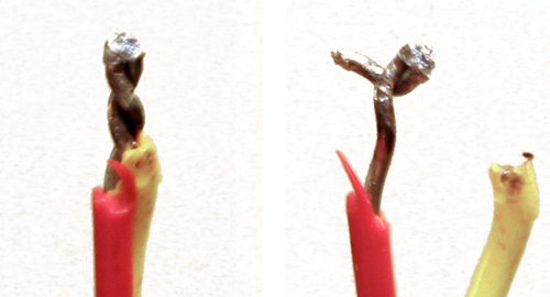
Welding instructions
Parts:
- Block of graphite, McMaster part 1763T23 ($10.70)
- Pair of conductive clips, McMaster part 7236K59 ($9.20 for 10) or equivalent
- Some fairly large gauge insulated wire (you can get that yourself or find it at McMaster)
- Fine needle-nose pliers with insulated handle
- A welder
Procedure:
Get a length of wire and put the conductive clips on both ends. Disengage the wire feed mechanism of your welder and set the wire feed to zero. Adjust the power on your welder (trial and error, I used “2”).
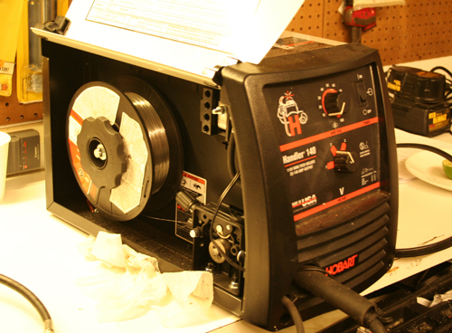
Attach one end of your wire to the tip of the welder’s copper electrode and the other to the metal part of your needle-nose pliers. Attach the welder’s ground clip to the graphite block. Twist the ends of your thermocouple wire together and hold them in the needle-nose pliers.
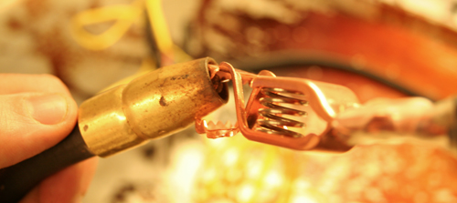
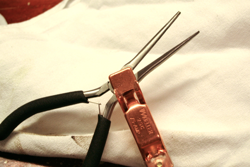
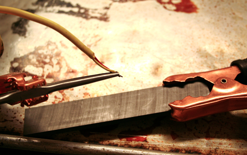
Pull the trigger on the welder and scratch the thermocouple wire across the graphite. The thermocouple will weld itself together. It’s even easier with an arc welder. I haven’t needed flux but I guess you could use some.

I like the article!
I had good luck welding small therocouples with the following MIG method:
1. Sharpen a short piece of 1/16″ TIG tungsten (Pure Tungsten)
2. Drill out the MIG tip to 1/16″ and tap and drill for a set screw (I used 6-32) to hold the tungsten in the MIG tip.
3. Bend thin aluminum sheet to make “tweezers” out of aluminum to pinch the thermocouple wire in a vice. The melted thermocouple wire won’t stick to the aluminum.
4. Strip thermocouple wire and twist the two together and clamp it in the aluminum tweezers with the twisted part sticking out.
5. Clamp the MIG ground clamp to the vice/aluminum tweezers.
6. With all wire removed from the MIG gun, pull the trigger to activate the shielding gas (I set up with pure Argon) and touch the sharpened tungsten tip to the twisted wire sticking out of the “tweezers”.
7. The arc will melt the wire sticking out down into a tiny ball. Adjust the protruding length of wire to get the right ball size. The shielding gas will keep the wire from oxidizing as it melts.
Nice! We don’t have a real mig at the school (FCAW only) so I can’t reproduce. Anyone with a real Mig take note.
Ok, I’ve looked into welding thermocouple wires a little more and I think a capacitive discharge welder can be made on the relative-cheap for those without welding equipment using parts available from Radio Shack. A high-current NPN transistor, ~2200 uF 30v cap (?), battery charger, and a push button switch would probably be the entire parts list. I’ll test and report back. I’m not sure shielding gas is needed for these hobby-grade junctions.
As an aside, I found that my TIG setup welds wire nicely. I set the current to the lowest setting, high frequency off, and DC Reverse polarity. I’ll be testing these junctions tomorrow on my Christmas ribeye roast!
Hey Beebe,
How did it work?
A hundred years ago, when I was an Engineering student, we used thermocouples, but always had the “cold junction” in a bath of heavily iced water. Unless the “cold junction” was at a precisely known temperature, the TC reading could not be calculated accurately.
Now-a-days, it seems like everyone uses TC’s without giving a thought to the cold junction… I guess they think that “ambient temperature” is constant enough. I can’t imagine using a TC in sous-vide unless there is a precisely known “cold junction” temperature, which usually is not the case.
My previous comment, perhaps, wasn’t clear enough. Thermocouples measure differences in temperature between the “hot” and “cold” junctions — not absolute temperatures.
Thus, if the kitchen temperature changes by 4 degrees, a TC without having its cold junction in an ice bath, will show a 4 degree “error”; not what you want in sous-vide.
Also, TC’s are not linear… so “calibrating” by zeroing at 32F will introduce further error. TC’s nonlinearity is highest around 100F (in the range of 32F-212F).
Using RTD’s is much more stable, being independant of ambiant temperature.
BTW thanks for making me seek out my dusty Engineering notes from almost 4 decades ago. Graduating from McGill U in Montreal was something I had almost forgotten. Strange that I love cooking.
Hello Tom M,
As I understand it, cold junction compensation in a thermocouple thermometer is accomplished with a secondary temperature sensor, like a thermistor, at the “cold junction” instead of an ice bath. I also think most thermocouples these days are linearized with lookup tables, but I could be mistaken.
Thanks Dave:
Of course you are right. The “Black Box†(BB) that the thermocouple (TC) is connected to, must translate mV to degrees temperature. The most straightforward way to do this would be to do a table look up. (Microchips are so cool!)
Let’s see how this would work. For a type K TC let’s use the National Institute of Standards and Technology (NIST) Tables in degrees Celsius available here:
http://srdata.nist.gov/its90/download/type_k.tab
For my first example, let’s assume the BB is really unsophisticated and that we’d need to have one TC junction in an ice-water bath (T=0C).
The other junction is in a liquid of unknown temperature. The BB sees that the thermoelectric voltage reading is 1.162 mV. Doing the table look up, the BB displays a temperature of exactly 40C.
So far so good!
Now, let’s assume the BB is a little more sophisticated and just needs to be calibrated by placing the probe in an ice water bath. (The other junction actually forms at the terminals of the BB and would be at room temperature, say, 21C.)
Now the BB notices that the voltage is -0.838 mV and stores this value as an offset, to be used when measuring unknown temperatures.
So now place the probe to measure an unknown temperature (I happen to know that the unknown temperature is actually 50C).
So now the “cold junction†(BB terminal) is at room temperature (21C) and the “hot junction†is at 50C.
Using the table look up again, we get
21C  0.838 mV
50C  2.023 mV
Δ  1.185
Thus, the BB sees an electric potential of 1.185 mV (2.023 – 0.838). But since we calibrated the probe the BB knows that whatever reading it gets, must be off-set by that value, so the BB adds 0.838 mV to the measured 1.185 mV and gets 2.023 mV. It does the table look up and displays the correct temperature of 50C.
So far, so good. Now, let’s assume the ambient temperature in the kitchen goes up by 4C (the ovens have heated it up) but the TC isn’t recalibrated. The thing whose temperature we’re measuring remains at 50C.
So now we have:
24C  0.960 mV
50C  2.023 mV
Δ  1.063 mV
The BB sees the 1.063 mV, but knows to add the offset previously determined (0.838 mV) and comes up with 1.901 mV. It now goes and does a table look up and displays the temperature as 47C.
So what exactly happened?? Ambient temperature went up 4C and we would have expected the reading to have gone down exactly 4C also. Instead, it went down only 3C.
The 1C difference is caused by the non-linearity of the temp vs. mV characteristic of the TC.
This leads us the next level of sophistication in the BB. It now has a thermistor which accurately measures the ambient temperature (i.e. temperature at the BB input terminal).
The thermistor correctly reports the room temperature as 24C. The BB does a table lookup and now knows to add, as the offset, 0.960 mV.
Thus it adds 0.960 mV to the 1.063 mV it sees (=2.023 mV) and again does a lookup and gets 50C, the correct temperature. Problem solved!
The only question outstanding is: do all BB’s, be they PIDs or whatever, have thermistor (or equivalent) compensation?
I would hazard a guess that the “high-end†ones do.
What about the other BB’s? Well, if their manuals say you must first calibrate the TC by using an ice bath, then this is surely an indication that thermistor compensation isn’t part of the BB and that both ambient temperature changes and TC non-linearity are problematic.
Sorry for being so long winded! I didn’t know how to make my point any better…
Wow.
I have to run an ice-batch test on mine and then change ambient, but I’ve never noticed a difference on temps (of ice baths) from room to room. I have, however, noticed a difference from probe to probe. I usually calibrate only when I put in a new probe. Each probe seems pretty consistent (precise at least, if not necessarily accurate). I haven’t checked the compensation on lower-end PID controllers. If it weren’t for the fact that thermocouple inputs were so ubiquitous, and thermocouples are easy to make (although few people make them), RTDs and other resistance based approaches are obviously much easier. It is rare we need the temperature highs and lows that a thermocouple can manage, and it is hard to interface a TC to a microcontroller without a dedicated amplifier (at least with an arduino).
Hi Dave:
Sounds like a great experient, i.e. measuring the temperatures of ice baths with the BB at different ambient temperatures.
That being said there is at least one error in my previous post. I said that if the BB manual suggests calibrating the TC in an ice-water bath, it probably indicates no thermistor compensation.
I was wrong. TC’s (of the same type) have minor metallurgical variations and the system response itself (TC wires + BB) that introduce various errors.
Thus, even ambient T compensated BB’s should recommend calibration.
Woe am I! It’s time for my sack-cloth and ashes routine, again.
Your experiment, though, still sounds very interesting and relevant.
BTW, the ubiquitous digital read-outs giving T to 0.1 degree, when the system itself probably is accurate to only plus/minus 1C are misleading. Funny what amuses me 😉